

Technical insight
How to Check Starter Battery Size, Terminals and Vehicle Fitment
Match starter battery dimensions, hold-down, terminal position, cable clearance, voltage and CCA before approving a sodium-ion replacement or fleet sample.
— title: “How to Check Starter Battery Size, Terminals and Vehicle Fitment” slug: “starter-battery-size-terminal-fitment-guide” status: “draft” language: “en” content_type: “technical fitment guide” primary_keyword: “starter battery size and terminal fitment” secondary_keywords:
- “car battery group size”
- “battery terminal position”
- “LN battery size”
- “starter battery dimensions”
- “sodium-ion battery fitment”
target_audience:
- “battery distributors”
- “auto-parts suppliers”
- “workshops and installers”
- “fleet maintenance teams”
search_intent: “informational and commercial investigation” meta_title: “Starter Battery Size and Terminal Fitment Guide | NaVolt” meta_description: “Match starter battery dimensions, hold-down, terminal position, cable clearance, voltage and CCA before approving a sodium-ion replacement or fleet sample.” author: “NaVolt Editorial Team” technical_reviewer: “Mr. Lu” last_updated: “2026-07-17” —
A starter battery is only a suitable replacement when its case, terminals, mounting system and electrical requirements all match the vehicle. A familiar group-size label helps narrow the search, but it does not confirm polarity, cable reach, hold-down engagement, bonnet clearance or charging-system compatibility.
For distributors and workshops, the safest sequence is straightforward: measure the installation, inspect the connection system, check the vehicle’s electrical requirements, then test a current production sample in the exact vehicle configuration.
The starter battery vs start-stop battery comparison should be used first when the required duty category is still unclear.
> Important terminal note > The current NaVolt 12 V specifications list an M6 bolt-type interface. An M6 connection is not automatically interchangeable with an SAE, DIN or JIS automotive post. Direct installation requires a validated cable lug, terminal adapter or vehicle-specific connection design.
A five-check fitment decision
- Electrical class: nominal voltage, required CCA, reserve duty and charging behavior.
- Case envelope: maximum length, width, height and any lid or handle protrusions.
- Connection: terminal type, polarity, cable lug, reach and insulation.
- Mounting: base flange, wedge, top clamp and surrounding clearance.
- Vehicle validation: crank, recharge, diagnostics, start-stop behavior and sleep current.
If any one of these checks fails, a shared group-size name does not make the battery a direct replacement.
What a battery group size can鈥攁nd cannot鈥攃onfirm
Battery Council International group sizes standardize maximum dimensions, terminal locations and related fitment characteristics. European LN, L and T references serve a similar cross-reference role.
These systems are useful catalogue filters. They are not vehicle-specific approvals. Regional versions of the same vehicle may use different trays, cables or energy-management settings, and an older vehicle may already contain a non-original battery. Treat the code as a shortlist, then inspect the installation.
Step 1: Measure the battery and tray
State the dimension order
Do not publish three numbers without defining their order. The current NaVolt B, D and H specifications present maximum dimensions as W 脳 D 脳 H; the LR-N100 sheet uses L 脳 W 脳 H.
For example, the H5 specification lists 245 脳 175 脳 190 mm, W 脳 D 脳 H. Keeping the source order beside the value prevents a buyer, salesperson or CMS editor from silently reversing two dimensions.
Measure the maximum envelope
Use a steel rule or calibrated tape for the case and tray. Use callipers where terminal, flange or mounting details need tighter measurement. Record:
- Maximum case length and width
- Case height excluding terminals
- Overall height including terminals, covers and lid features
- Base flange and hold-down profile
- Handle, vent and cable-cover protrusions
- Service clearance above and beside the installed battery
A few millimetres can decide whether a base wedge engages or a terminal cover touches the bonnet. Photos with a ruler in frame are often more useful than an unlabelled number in an email.
Step 2: Check terminals, polarity and cable routing
Define the viewing direction before using phrases such as 鈥渓eft positive.鈥?A workable record might say: 鈥渢erminals closest to the viewer, positive on the right.鈥?Add a reference photo whenever possible.
Then document the connection itself:
- Positive and negative terminal positions
- SAE/DIN/JIS post, stud or threaded interface
- Thread size, terminal height and contact surface
- Cable-lug hole size and allowable torque
- Cable reach, bend radius and strain
- Insulating-cover clearance
Do not assume an adapter solves every mismatch. The adapter must carry cranking current, remain mechanically secure and preserve insulation and service clearance. Check whether a tool, clamp or bonnet panel could bridge the positive terminal to ground during installation or operation.
Step 3: Verify hold-down and enclosure clearance
A case can sit inside the tray and still be unsafe under vibration. Inspect the tray lip, wedge, bolt position and base-flange profile. If the vehicle uses a top clamp, make sure it loads the intended structural area rather than the lid, BMS cover, terminal or service feature.
Also check the space needed to remove the battery. A fitment that requires excessive cable tension or removal of unrelated vehicle systems is a service problem waiting to happen.
AGM and EFB batteries are sometimes installed in enclosed luggage compartments or beneath seats and may use vent connections. A chemistry change still requires review of enclosure temperature, drainage, sealing, ventilation and fault behavior. Physical fit is only one part of that decision.
Step 4: Check electrical compatibility separately
A battery that fits the tray is not automatically compatible with the vehicle. Confirm:
- Nominal system voltage
- Required CCA and the applicable test standard
- Engine-off accessory and parking loads
- Alternator or DC-DC charging behavior
- Battery-monitoring sensor
- Registration or coding procedure
- Start-stop and regenerative-braking strategy
The current NaVolt 12 V product specifications confirm a 15.8 V charge voltage and a 6 V discharge cut-off. Fitment approval must confirm that the actual alternator or DC-DC profile is compatible with the battery charging requirement; this does not mean every compatible vehicle holds 15.8 V continuously.
When the project changes from AGM to sodium-ion, the AGM start-stop battery replacement guide provides the additional charging, BMS and vehicle-validation sequence.
How NaVolt product and fitment records should be used
NaVolt keeps two records because they answer different questions.
| Record | What it controls | H5 example |
|---|---|---|
| Current product specification | The battery being manufactured and supplied | 245 脳 175 脳 190 mm, 40 Ah 卤5%, 850 A CCA, M6 interface |
| Current vehicle-fitment table | Case-reference dimensions, 25°C CCA, cold-start CCA range, cross-reference names and example applications | 247 × 175 × 191 mm reference; 850 A at 25°C; 650–850 A cold-start range; LN2/L2/T5/Group 47; example Volkswagen, Audi, BMW and Ford applications |
The current fitment table can identify a candidate, but it is not a universal guarantee for every year, engine and market. Its reference dimensions and CCA fields must remain separate from the current product specification. Final approval still belongs to the current production sample and the exact vehicle.
Current NaVolt 12 V case and electrical references
| Model | Capacity | Current CCA | Maximum dimensions | Interface |
|---|---|---|---|---|
| B19-12V-500 | 20 Ah 卤5% | 500 A | 192 脳 128 脳 222 mm | M6 bolt type |
| B24-12V-660 | 30 Ah 卤5% | 660 A | 238 脳 130 脳 222 mm | M6 bolt type |
| D23-12V-850 | 40 Ah 卤5% | 850 A | 231 脳 175 脳 222 mm | M6 bolt type |
| D26-12V-850 | 40 Ah 卤5% | 850 A | 261 脳 173 脳 223 mm | M6 bolt type |
| D31-12V-1000 | 50 Ah 卤5% | 1,000 A | 306 脳 173 脳 222 mm | M6 bolt type |
| H4-12V-400 | 30 Ah 卤5% | 660 A | 207 脳 175 脳 190 mm | M6 bolt type |
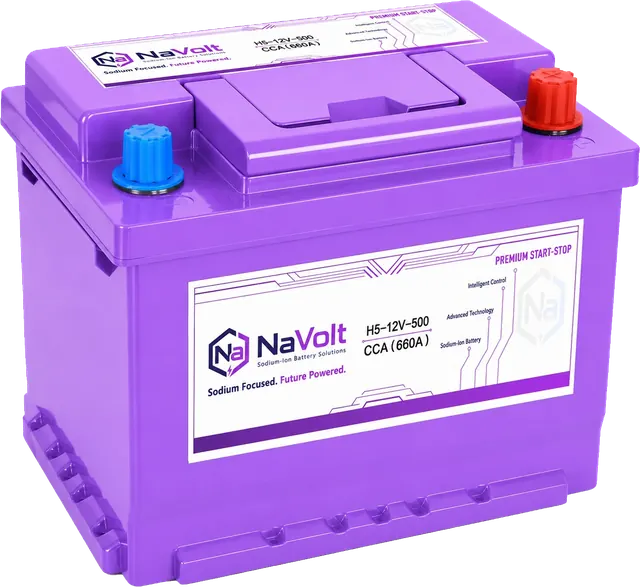
| H5-12V-500 | 40 Ah 卤5% | 850 A | 245 脳 175 脳 190 mm | M6 bolt type |
| H6-12V-600 | 50 Ah 卤5% | 1,000 A | 281 脳 175 脳 190 mm | M6 bolt type |
| H7-12V-750 | 60 Ah 卤5% | 1,200 A | 315 脳 175 脳 190 mm | M6 bolt type |
| H8-12V-840 | 70 Ah 卤5% | 1,400 A | 354 脳 175 脳 190 mm | M6 bolt type |
| H9-12V-900 | 80 Ah 卤5% | 1,600 A | 410 脳 175 脳 190 mm | M6 bolt type |
All dimensions in this table use the W 脳 D 脳 H order stated in the current specifications. The model suffix is an identifier; use the CCA column for the current electrical value.
Workshop fitment checklist
Installation and vehicle-system testing should be completed by a qualified technician following the vehicle manufacturer’s service procedures.
Before selecting a sample
- Photograph the original battery label, tray and cable layout.
- Record vehicle make, model, year, engine and destination market.
- Measure the battery, tray and overhead clearance.
- Record polarity, terminal system and hold-down design.
- Confirm voltage, required CCA and engine-off load.
- Record charging-voltage behavior and registration requirements.
Before connecting the battery
- Compare the sample with the current drawing or specification.
- Check for transport damage.
- Verify polarity with an appropriate instrument.
- Confirm the lug or adapter, contact area and specified torque.
- Fit terminal insulation and engage the hold-down fully.
- Route cables without tension or contact with sharp or hot surfaces.
During the vehicle trial
- Measure crank voltage and restart behavior.
- Record charging voltage and current across operating states.
- Check diagnostic codes and battery registration.
- Verify start-stop operation where applicable.
- Measure sleep current and confirm wake behavior.
- Reinspect terminals and mounting after the agreed trial period.
Frequently asked questions
Is the same group size always a direct replacement?
No. It is a useful shortlist, not an installation approval. Dimensions, terminals, polarity, hold-down, cable clearance, voltage, CCA, charging behavior and vehicle coding still need to match.
Do M6 terminals fit standard automotive posts?
Not without a validated connection design. The installer must confirm the lug or adapter, contact area, current capacity, torque, insulation and available clearance.
Does a higher CCA rating guarantee compatibility?
No. Higher CCA may add cranking margin, but it does not correct an incompatible case, reversed polarity, unsuitable charging profile or poor BMS interaction.
Can a sodium-ion battery directly replace AGM or EFB?
Not on size or CCA alone. Review the terminal interface, mounting, charging profile, battery monitoring, start-stop logic and any vehicle coding requirement before approving the replacement.
Can the current fitment table approve a vehicle by itself?
No. It provides case references, CCA fields and example applications for shortlisting. The current production sample, terminal solution, charging profile and exact vehicle configuration still need confirmation before a fleet, distributor or warranty programme is approved.
Conclusion
Good fitment work is deliberately uneventful: the case sits correctly, the clamp engages, the cable is relaxed, the terminal is insulated and the vehicle behaves normally after installation. Group-size codes can get a buyer to the right shelf; measurements and vehicle testing decide whether the battery belongs in the vehicle.
Review NaVolt starter and start-stop battery categories before shortlisting a sample. To approve an application, request a fitment review and include the original battery label, vehicle details, tray measurements and clear terminal photos.
Sources
- Battery Council International, BCI Group Sizes.
- NaVolt 12 V Sodium-Ion Battery Technical Specifications, current revisions.
- NaVolt Vehicle Fitment Table, controlled revision dated July 19, 2026.